About VantEdge
RF Noise Mapping in Campus Environment • IEEE AP-S Project
1. About the Team
Team VantEdge – IEEE AP-S (BMSIT&M)
Jishnu K
1BY24EC069
Chinmay Ravindra Gowda
1BY24EC037
Arnav Paniya
1BY24EC026
Adithya S P
1BY24EC007
Areas of Contribution
2. About the Project
VantEdge is a cutting-edge initiative designed to address the invisible challenge of Radio Frequency (RF) noise in educational campuses. Our system utilizes a network of ESP32-based multi-node sensor devices to monitor, log, and visualize RF noise levels, interference, and signal strength across the BMSIT&M campus.
Why this matters: As wireless dependency grows, signal interference becomes a critical bottleneck for connectivity. Our solution helps network administrators optimize WiFi networks, identify dead zones, and detect interference-heavy areas, enabling data-driven smart-campus planning.
Approach: The system deploys multiple portable nodes equipped with GPS for automatic geotagging. Data is stored locally on SD cards for redundancy and uploaded to the cloud for real-time processing. The result is an interactive dashboard that provides a live heatmap of the RF environment.
Key Features: Portable • Low-cost • Battery Powered • Future-ready
3. Components Used
- ESP32 NodeMCU: The core microcontroller responsible for WiFi scanning and data processing.
- NEO-6M GPS Module: Enables automatic geotagging of every signal reading for precise mapping.
- SD Card Module: Provides dual storage capability, ensuring data is saved even without internet connectivity.
- Antenna (2.4 GHz): Enhances RF reception sensitivity for more accurate noise detection.
- Li-ion Battery + Charge Controller: Ensures the system is fully portable and rechargeable.
- OLED Display (SSD1306): Shows live device statistics and connection status in the field.
- Solar Support: Designed with future-ready power inputs for sustainable operation.
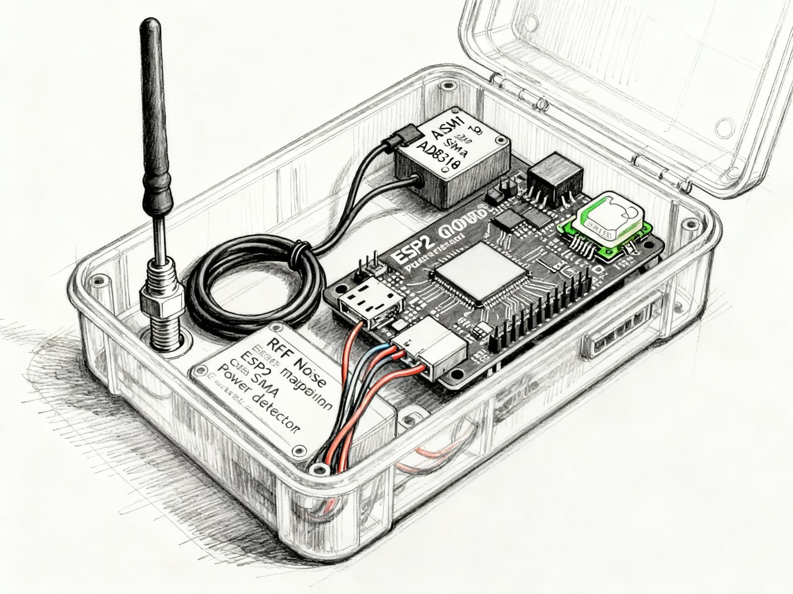
“System circuit diagram – ESP32-based RF monitoring unit.”
4. Real-World Applications
Campus-wide RF noise heatmapping
Detecting poor WiFi zones
Identifying interference-heavy areas
Improving network planning for events/exams
Research & lab demonstrations
Deployable in smart cities, malls, & airports
5. How the System Works (Technical Flow)
6. What Makes Our Solution Unique (UVP)
Cost & Efficiency
Significantly lower cost than bulky industrial RF survey tools, making it accessible for educational and research purposes.
Automation
Automatic GPS tagging eliminates manual errors (unlike older manual methods), ensuring high-fidelity data.
Resilience
Works offline due to SD card redundancy and features long battery life with future solar support.
Scalability
Multi-node simultaneous sensing allows for rapid coverage of large campuses. Fully open-source for research.